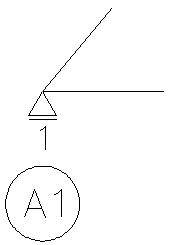
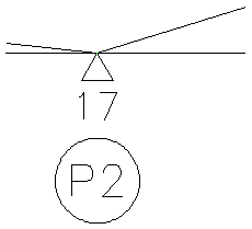
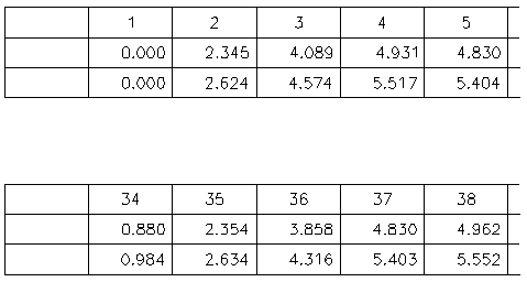
Draw camber . Program name : CAMBER.LSP
Most of the materials of the bridge are made of concrete or steel. Even if We make the bridge straight, the middle part of bride will be bended down due to its own weight. So civil engineers got one idea. When We make the upper structure, We make it bend upside in advance. Of course, the bending up height is equal to the amount sagging by its own weight. That way, the convex top becomes a straight structure due to its sag caused by its own weight. So designer draw camber drawing to tell contractors the volume rises (Camber) and the shape of the camber. this is annoying. Because we must reverse the sign of the amount of deflection due to self weight and change the unit of meter to cm (or mm) . The problem is that the aspect ratio is different. What happens if you draw an elevation with an aspect ratio of 1: 1? The bridge is long and the deflection is small. Eventually the amount of rise in the picture will not be displayed. That's why you must draw a few decades of deflection. And one more thing ... you need to make a Camber table. I'm tired of writing numbers. Camber drawing looks simple(actually it is simple). This is the best item to program. Simple repetitive work! CAMBER.LSP was born to solve this inconvenience. In other words, it reads data file and draws camber and camber table. You can create data file by appropriately editing the deflection of the structural analysis ouput, and then Run CAD and executes CAMBER.LSP. Let's look at an example of use ~ Example LEFT MARGIN (mm)<60>: [Enter left margin between border and camber drawing] 41-NODE / 2-CAMBER(S) / 1-COMBINATION(S) / 1-DRAWING(S) FOUND [Select data file using dialog box.] Column width (mm)<20.0>: [Enter width of CAMBER TABLE column]
Enter Factor of Value <1.0>: [Enter scale factor(For example data is m unit and you want to use mm unit Enter 1000)] Enter Precision <3>: [Enter number of digit of Camber value]
- data file -
- 1, 0.0, 0.00000, 0.00000,A1 2, 1.0, -0.02345, -0.02624 3, 2.0, -0.04089, -0.04574 4, 3.0, -0.04931, -0.05517 5, 4.0, -0.04830, -0.05404 6, 5.0, -0.03870, -0.04330 7, 6.0, -0.02362, -0.02642 8, 7.0, -0.00883, -0.00988 - 9, 8.0, 0.00000, 0.00000,P1 10, 9.0, 0.00037, 0.00042 11,10.0, -0.00678, -0.00758 12,11.0, -0.01522, -0.01703 13,12.0, -0.01931, -0.02160 14,13.0, -0.01713, -0.01916 15,14.0, -0.00983, -0.01100 ¢Ö |
16,15.0, -0.00212, -0.00238 +17,16.0, 0.00000, 0.00000,P2 18,17.0, -0.00615, -0.00688 19,18.0, -0.01752, -0.01960 20,19.0, -0.02764, -0.03092 21,20.0, -0.03151, -0.03525 22,21.0, -0.02764, -0.03092 23,22.0, -0.01751, -0.01959 24,23.0, -0.00615, -0.00688 -25,24.0, 0.00000, 0.00000,P3 26,25.0, -0.00213, -0.00239 27,26.0, -0.00985, -0.01102 28,27.0, -0.01716, -0.01920 29,28.0, -0.01935, -0.02164 30,29.0, -0.01526, -0.01707 ¢Ö |
31,30.0, -0.00682, -0.00763 32,31.0, 0.00035, 0.00039 -33,32.0, 0.00000, 0.00000,P4 34,33.0, -0.00880, -0.00984 35,34.0, -0.02354, -0.02634 36,35.0, -0.03858, -0.04316 37,36.0, -0.04830, -0.05403 38,37.0, -0.04962, -0.05552 39,38.0, -0.04126, -0.04616 40,39.0, -0.02364, -0.02645 -41,40.0, 0.00000, 0.00000,A2 COMB 1+2 draw 1,2,3 |
¡á CAMBER data description ù¹ø°ÁÙÀÇ - 1, 0.0, 0.00000, 0.00000,A1 | | | | | +--- ¨ç Abut/Pier Number | | | | +------- ¨è deflection value 2 (result of analysis) ¡ØNotice: Not camber | | | +---------------- ¨é deflection value 1 (result of analysis) | | +----------------------- ¨ê x coordination of node | +--------------------------- ¨ë node number +----------------------------- ¨ì - : sliding bearing + : fixed bearing
after second row.. use same concept ¨ç Abut/Pier Number [Mark of Abut/Pier ] ¨è deflection value 2 (result of analysis) [You can enter several deflection value. for Example, before composite , after composite. ¨é deflection value 1 (result of analysis) [You can get this data modifying output file of analysis] ¨ê nodeÀÇ X ÁÂÇ¥ [ " ] ¨ë node¹øÈ£ ¨ì - : °¡µ¿´Ü Ç¥½Ã [sliding bearing(-), fixed bearing(+) should be first column] + : °íÁ¤´Ü Ç¥½Ã [Abut/Pier number should be at the end if +/- is at the first column] ¡á combination and draw command ¢º COMB You can combinate previous cases at next low of COMB command. for Example if You enter two Camber previous, combinated case that after COMB command become third case. COMB 1+2 ¡çcase-1 plus case-2, New case become case-3 1+3 ¡çcase-1 plus case-3, New case become case-4. you can use case that is combined previous
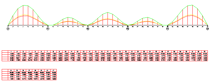
¢º DRAW This command draws basic cases and combination cases. You can define one drawing per a line under the DRAW command. For example, If you define 1,2,3 on the next line of DRAW command Program draws 1,2,3 cases in a drawing. If you want to draw separately, define a case per one line, The drawing drawn with the above data is shown below.
Notice : ¡ß X-length of camber drawing is setted to size of border. ¡ß If the length of Camber table is longer then camber drawing, Table is seperate two or more number and layed upper and lower. ¡ß Low height of Camber table is 7mm. ¡ß Height if text is 2.5mm.